Electronics Update
Ageing processors
The ageing chart plotting computer has been with us for almost 8 years, and although it has served us very well during that time, it has been struggling with displaying charts in areas with intricate coast lines. The old display is also not the most efficient since it has a mains power input, which means the 12V DC ship supply first needs to be converted to 230V AC using an inverter, only for the internal power supply in the display to convert the power back to something very close to the ship's supply.
Modern mobile processors such as the ones used in the Raspberry Pi 4 have benefited from the intense demand for more powerful and more efficient smartphones. Modern processors are much better at regulating their power consumption according to their workload resulting in much lower idle power consumption.
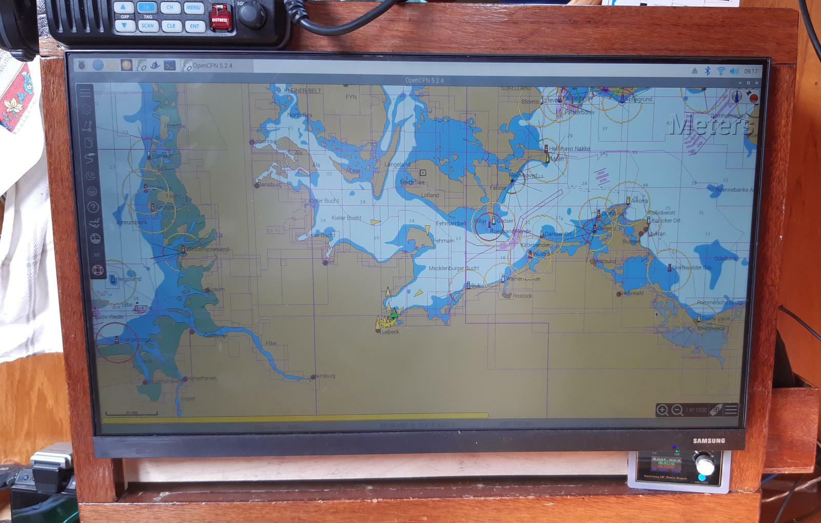
Choosing a new display was not so easy since it needs to fit into a very specific space with the existing shelf on the chart table and have an external power supply. After quite a bit of research Hauke found one that fits just right as it has:
- A VESA mount (to securely mount it, without the need for a stand)
- DC 14 V in
- Connectors facing down to maximise space behind for storage
- No wider than the box (520 mm)
- A very low power consumption
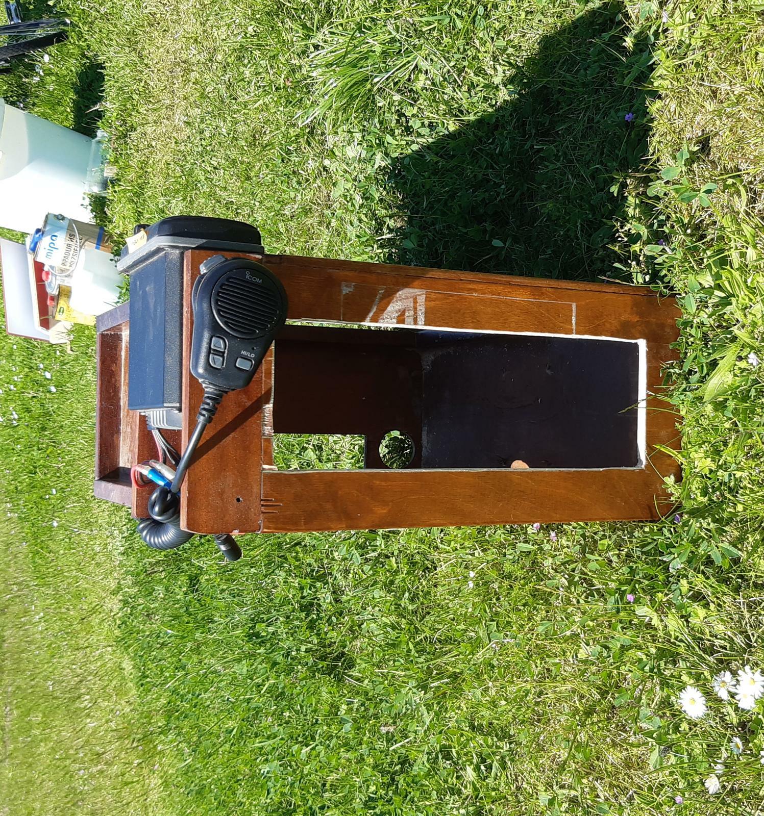
Storage space is always scarce on a boat, so we wanted to make better use of the space behind the display and cut a hole in to the side of the "display box" to be able to use it as another small cupboard.
Although the display would probably work straight off the 12V ship supply, we wanted to stabilize its power supply a little bit and got an inexpensive adjustable supply off eBay, which also lets you monitor its power consumption and switch the power off.
Signal confusion
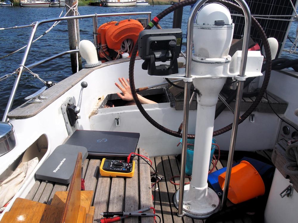
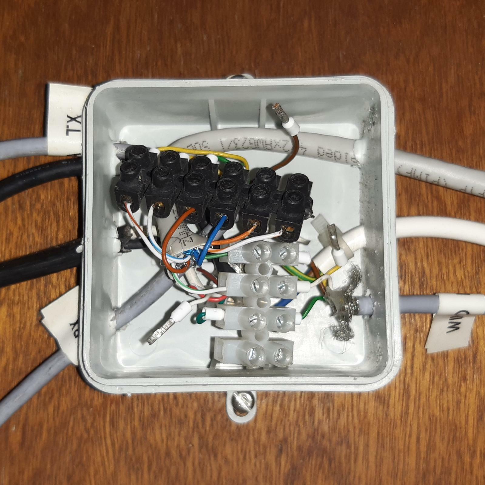
Of course the new computer had to be reconnected to the rest of the Goden Wind's electronics. When starting on this task we would not have guessed how many hours Hauke would spend wedged in the tight space underneath the cockpit (some of you might know this as the beer storage area). Stuck in there with a laptop and a signal analyzer he was trying to make sense of the partially labelled and bunched wires coming from various devices into a small junction box.
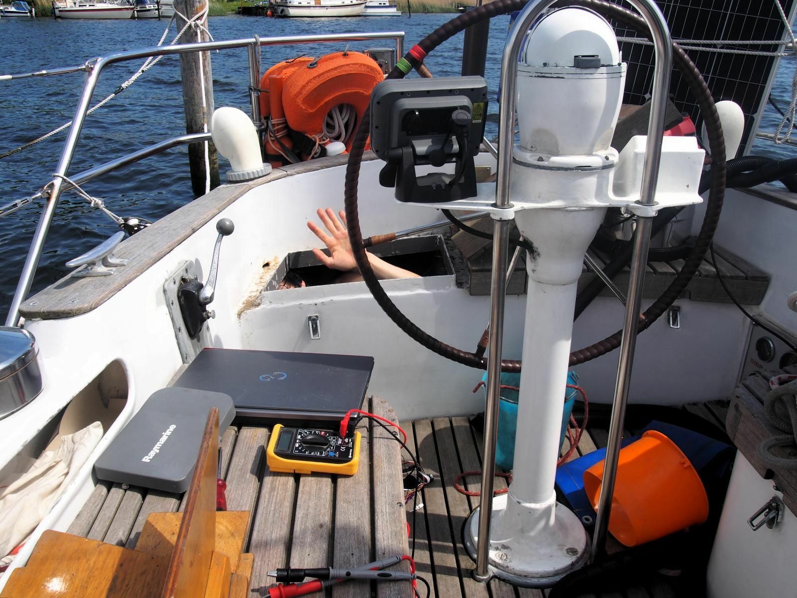
Try as he might, Hauke could not get things to communicate properly, sometimes just pressing on some of the cables would make it work for a few seconds, only then, when letting go, the data would stop flowing.
There are many different standards for devices on ships to communicate with each other, most manufacturers having their own proprietary standards. The most widely used one is known as NMEA of which there are two versions: NMEA0183 and NMEA2000. NMEA0183 is the older of these standards and has been revised over the years. Older devices (such as the chart plotter and Windex) use a single wire to transmit their signal referenced to ground where anything lower than +0.5 V is considered a binary '0' and anything above +4.0 V is considered a binary '1', which is related to, but does not fully comply with RS-232. Newer devices (such as the AIS Transceiver) use a differential signal defined as RS-422, where one wire carries a 'positive' version of the signal (identical to the RS-232 type) and the other a negative version, which means it is much less sensitive to electrical noise and can be transmitted over much longer distances.
On top of that, there are two different speeds at which the data is commonly transmitted. This is known as the baud rate and for NMEA 0183 it is either 4800 or 38400. Most devices use the lower data rate, except for AIS which needs to transfer a lot of information about the speed and heading of all the vessels within range.
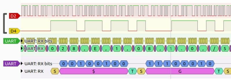
As you can imagine all these different signals can be quite difficult to unify. Fortunately, they are compatible with one another, as the positive signal of the RS-422 standard is close enough to the RS-232 signal. However, all devices can usually be made to communicate with each other if connected and grounded properly.
Armed with the proper know how, he decided it was better to start with a clean slate and pulled out all the cables and re-soldered a much longer and properly labeled cable to avoid this annoying junction in such an inaccessible location. Now the outside plotter is directly connected to the computer, something Hauke thinks probably should have been done a long time ago. Finally, no more fiddling with annoying screw terminals in cramped spaces. With clearly documented colours and a good idea of which signal wires need to be connected and which ones grounded, everything works like a charm!
Software Base
As big fans of open source software it was a delight to discover the OpenPlotter project, which integrates all the essential navigation software (such as OpenCPN, a signal server, nav dashboard and much more) in to one handy Raspberry Pi image. Installing it is as easy as any other Raspberry image and just involves copying it to a microSD card and plugging it in. The serial inputs and outputs are handled by small USB to RS-422 adapters, which are available from eBay for less than 3€ a piece.
Fortunately, Hauke discovered a post from Bruce of the SV Matilda which points out, in his detailed guide on how to install OpenPlotter, that the polarity marked on those adapters is wrong. This was a lucky find that cut down several hours of tinkering time.
Even though we are not yet using many of the features of this "boat operating system" it provides an excellent base to develop things like wireless connectivity, a less expensive autopilot, radar and many more projects to come in one central place.

